Variable Message Sign publications
The scope of the VMS publication developed in DATEX II is to deliver VMS messages and status information among centres, both for information delivery purposes to make any interested client aware of the information published on a VMS, and also to support collaborative ITS services managing VMS messages based on information exchange of other type such as specific road situations or traffic data or travel times, or any further road management condition which could be useful to publish on VMS to road users.
To make this possible, two DATEX II publications have been developed:
a VMS Table Publication: to deliver information about VMS static data, such as location, static characteristics, specific static management information
VMS Status Publication: to deliver real time information about VMS information, such as the VMS working and eventual fault status, the displayed messages or pictorial information displayed, and any further dynamic information
As VMS can be defined as a display panel used to display one or more messages (text, symbols, pictograms or combinations) that can be changed or switched on or off as required.
There are currently a few options of VMS types, some are an assembly of specific components named display areas designed to display only a text, or to display generic images, which may be be implemented only in some predefined colours ( e.g. amber orange) or with full colour capabilities.
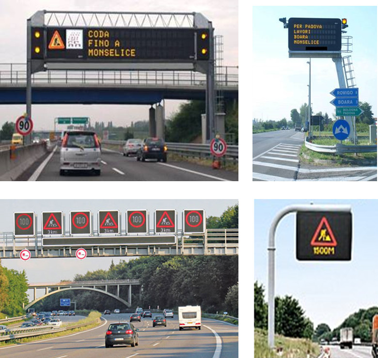
Figure: VMS with preassembled textual and pictogram display areas composition
Full matrix VMS allow textual information and graphics to be freely combined by dynamic VMS configuration.

Figure: Full matrix VMS examples
Smaller dimension mobile VMS are also possible, those can be placed at specific location to deliver information to road users in case of specific trouble or danger conditions which may arise in specific cases such as roadworks, accident repair works, or rerouting in operation.
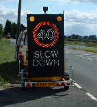
Figure: Mobile VMS
VMS can also have further characteristics for specifically designed VMS, below some examples which are used to display network status, travel times, parking optionally combined with traffic information, fuel information, etc.
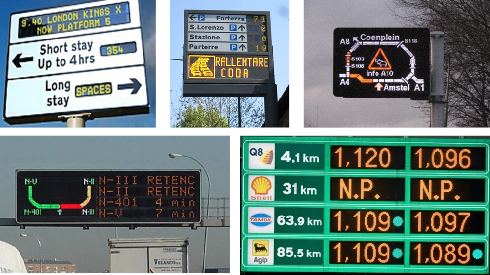
Figure: Specific usage taylored VMS
Vms Model
The VMS model has been designed with reuse of existing classes and datatype from Common and Location Referencing packages. The information displayed in a VMS message could also depend on information which is published in real time information such as situation information; the reference to this information is not explicit but can be enabled by a reference to situation or situation record information by its simple or versioned identifier.
VMS namespace dependencies
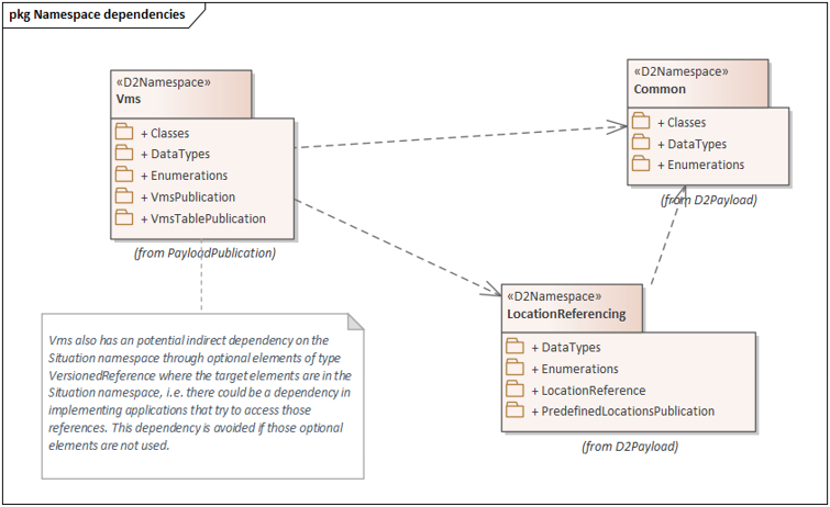
Figure: VMS Namespace relations and dependencies
The packages used to set up the VMS model have been built having in mind the option of possible reuse and classifying the VMS information based on static data, information about VMS characteristics which may be static or dynamic, configuration setting of the VMS to enable the VMS to display a message, either static or dynamic, and the message configuration itself which may have options to deliver one message or multiple messages which can be set.
VMS model package structure
VMSPublication and VMSTablePublication are the packages which define the main classes which allow VMS related publications to be instantiated.
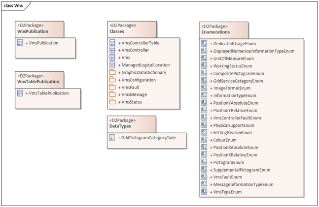
Figure: VMS model packages structure
VMS Table Publication
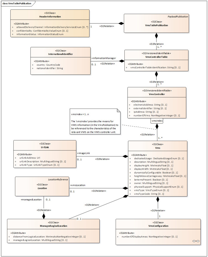
Figure: VMS Table diagram
A VMS table publication is a container for a number of VMS controller tables which may be instantiated for the need of several VMS manager such road operator or traffic management centre which own and/or manage a number of VMS. VMS controller tables are identified by a versioned identifier to allow referencing in the dynamic VMS publication. Adding a new VMS controller, or updating any VMS controller or VMS or their linked classes information, leads to a new version of the table to be instantiated, where all updated VMS controller entities have a new version number (while VMS controllers which have no update retain their previous version number).
A VMS controller is a versioned identifiable entity which controls a number of VMS which are associated with the VMS controller and identified by an index number. A VMS controller can have specific information associated such an IP address, and the number of controlled VMS, an internal application identifier and electronic address managed by the physical connection as well, depending on the technology.
Any VMS associated with a VMS controller may have specific information which are classified as information about its physical characteristics such as dimensions, construction and installation characteristics and possible optional devices associated with the physical VMS. An image can be associated to show the physical characteristics of the VMS.
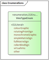
VMS may have a static physical location associated, but some VMS are mobile and they may not have such static information. The managed logical location is used for VMS whose physical position could lead to several paths yet which are used for a dedicated location that is not strictly the physical position.
Some of the relevant information of a VMS are the VMS type and the dedicated usage when set.
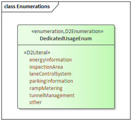
The VMS configuration
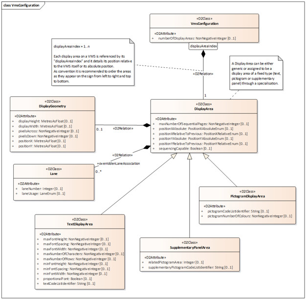
Figure: VMS Configuration Diagram
The VMS configuration diagram assembles the classes which deal with the VMS characteristics which can be both static or dynamic depending on the specific technology used to build the VMS: as shown in VMS general information, traditional VMS are comprised of predefined textual and pictogram display areas, while full matrix VMS are capable of a complete dynamic configuration of the panel area in such text or pictogram display areas to show structured composition of graphic signs and textual information.
A VMS configuration identifies several display areas which have a specific spatial and geometric information such as dimensions in length unit or in pixels as well as an absolute or relative position one each other when more than one display area is built.
A specific display area can be associated to a specific lane at the VMS location.
As specified by the hierarchy a display area can be a text display area, a pictogram, or a supplementary panel area.
The one to several display areas are identified by an index number which may be introduced following a convention to harmonise among the implementations, left to right and top to bottom VMS navigation as shown in the below figure.
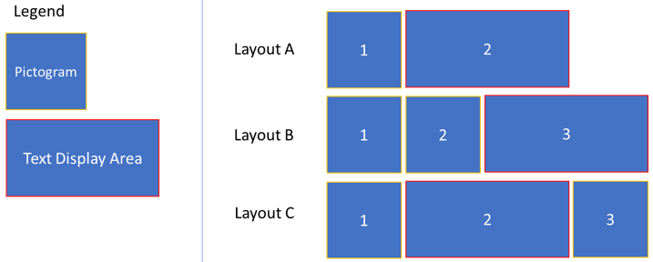
Figure: Display areas numbering for pictogram and textual compound VMS
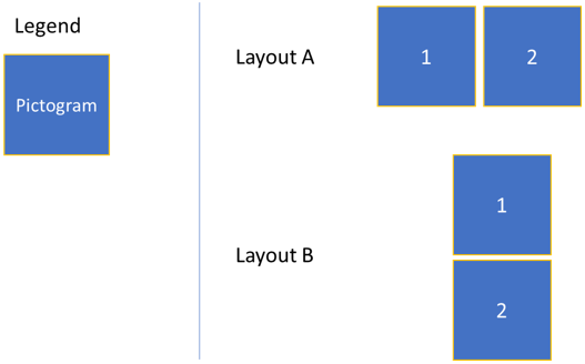
Figure: Display Area Numbering options for dual pictogram VMS
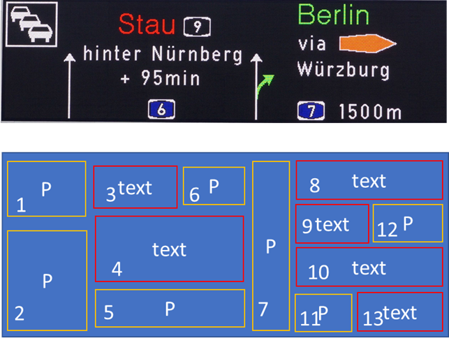
Figure: Display Area Numbering of a composite full matrix VMS with several textual and pictogram display areas
Supplementary panel display areas are specific display areas which are dedicated to give information about the displayed pictogram, so they are usually underneath a pictogram. Those information are typical in many road signs and the implementation is different among specific VMS suppliers; in some cases the supplementary information is embedded in the main pictogram itself so no dedicated supplementary panel is needed.
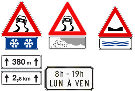
Figure: Examples of supplementary panel used in road signs
VMS Publication
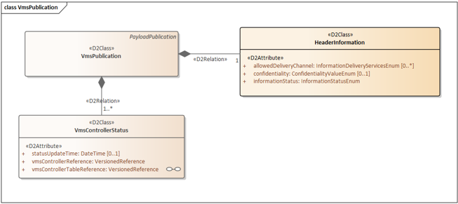
Figure: VMS publication diagram
VMS publication allows the delivery of VMS Controller and its controlled VMS working status and displayed messages.
VMS Fault
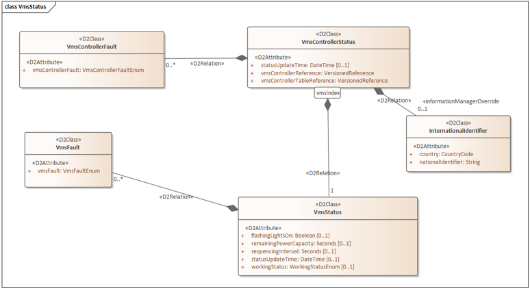
Figure: VMS status and fault classes
VMS controller fault and VMS faults are associated with the relative classes. A general VMS working status can be delivered to ensure the overall VMS capability to deliver the message to the road users besides the fault details; special maintenance status values are also possible when a VMS is not in use for maintenance purposes.
To reference each VMS the same index which had been introduced in the table is used.
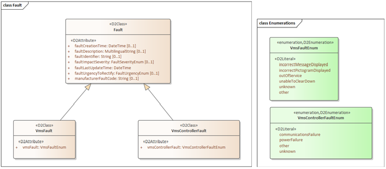
Figure: VMS Fault diagram and information
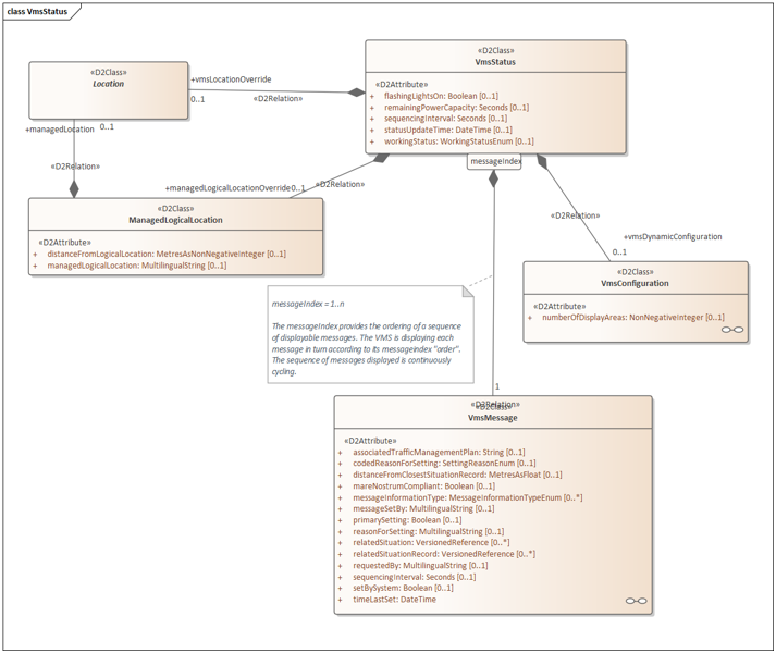
Figure: Status, dynamic Configuration and Messages
Any VMS may have specific location, both physical and logical, and configuration information which is necessary when not provided in the VMS table for dynamic information. For mobile VMS battery level information can be delivered as remainig power capacity.
Any VMS can display one or more Messages which are associated through the link to the VMS Message class. When multiple messages are shown by the VMS a message sequencing interval attribute is to be set. Flashing light.
VMS Message
One or more VMS messages can be displayed by a specific VMS as stated in previous paragraph. A single VMS can be visualised also by an image which can be delivered in the message.
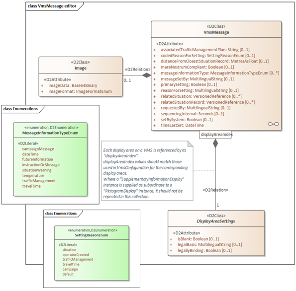
Figure: VMS Message Structure
A VMS message is considered as the overall information displayed by a VMS which is expressed by a collection of DisplayAreaSettings which apply to the display areas defined in the VMS configuration information. The index used in the display area setting will be the same which had been introduced in defining the VMS display panel in the configuration information.
A VMS message can be set by different road information delivery purposes and the message information type and reason for setting allow specification of the general purpose for which the message was created. When the information is about a specific situation on the road, the related situation or situation record can be delivered.
As a VMS display can be a single page or can be split among multiple pages.
A multi-page message enables the delivery of display setting for all the pages implemented by the display area. In this case a sequencing interval for the pages is set.
The following figures identify in different coloured frames the specific classes which are used to convey the display area setting for specific VMS display areas.
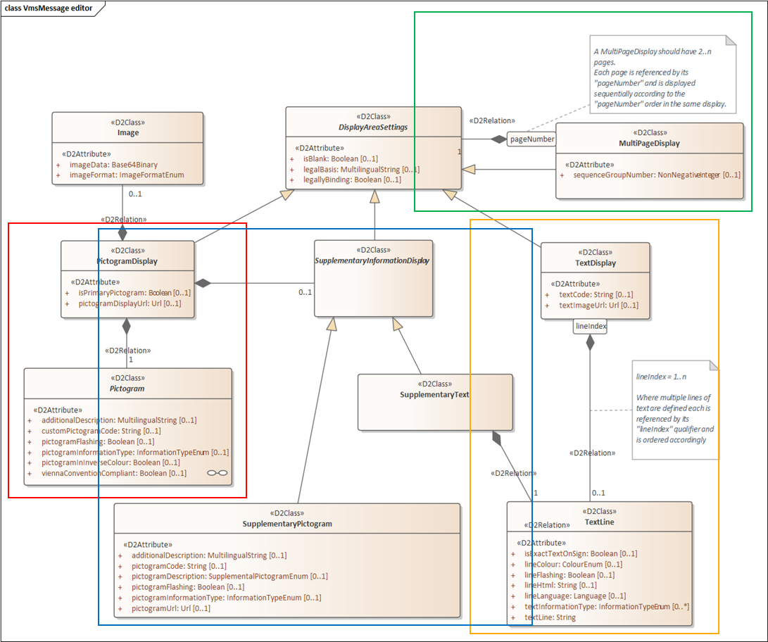
Figure: VMS Message Display Area Setting Diagram
Text Display: is comprised of text lines (identified by a line index) which may have different font size characteristics and be expressed in different languages; when needed a specific setting for the text information can be delivered, such as colour, or specific fonts attributes in a HTML description. Text code reference can be used for some devices, and a text image URL can be associated to retrieve an image associated with the overall text itself. The types of information contained in the text can be specified.
Pictogram Display: is used to display a graphic pictogram (described in the following section). An additional image can be delivered, representing the information displayed by the pictogram.
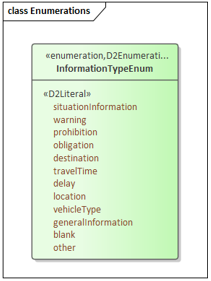
Figure: Information Type Enum
Supplementary Information Display: allows the definition of information displayed by a supplementary panel display area: it can be a graphical pictogram chosen from a set of supplementary pictogram types (addressed in pictogramDescription), or a single line text. The pictogram information type allows the delivery of information about the graphical meaning.
Pictogram Information
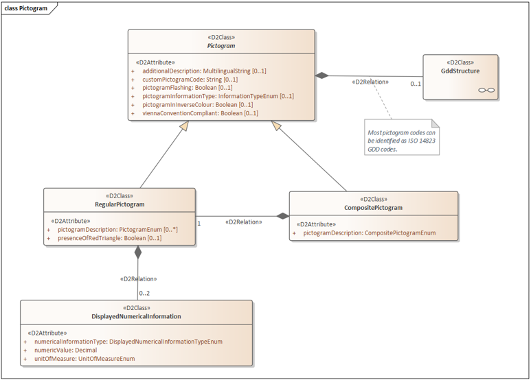
Figure: Pictogram diagram
A Pictogram is the graphic information which can be displayed on a pictogram display area.
Pictogram graphics are used to implement a sign or image which may help road user to understand the VMS message overall situation, so 1 or 2 pictogram can be used to address a situation and its major cause, or advice for network operation and rerouting advice.
Road sign graphics are mostly coded by GDD, which is an ISO standard coding which implements a standardised Graphical Data Dictionary, so a Pictogram can be defined by its GDD reference code which will be explained in the following paragraph. But GDD does not yet map all possible symbols which are used in practical VMS operation, such as non-road code signs or special symbols for newly developed information or services displayed on VMS. A predefined code pictogram description can deliver some known pictograms which are not managed by GDD; other information can be delivered as custom pictogram code with its multilingual string description.
Displayed numerical information can be associated to the regular pictogram and can be managed in the relative class with the appropriate unit of measure: e.g. vehicle weight, speed limit, distance among vehicles.
Composite pictograms are used to describe two graphical signs combined in the same graphics as shown by the following diagram and sample figures:
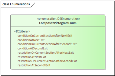
Figure: Composite Pictogram enumeration
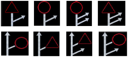
Figure: Composite Pictogram patterns

Figure: Composite pictures implementation samples
Graphical Data Dictionary coding
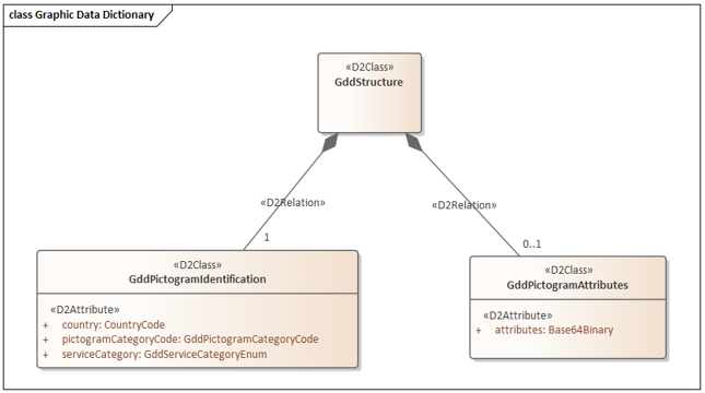
Figure: GDD Diagram
GDD classes are used to allow the ISO 14823 coding for road graphic signs. The GDD encoding is an aggregation of a GDD pictogram identification by a structured set of information: country code, service category chosen from a list and pictogram category number which is a 3-digit code to identify a pictogram, as defined in ISO 14823 Graphic Data Dictionary.
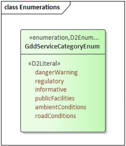
Figure: GDD service category enumeration
Besides GDD code there are several information which can be expressed in the graphic sign, such as speed limit, weight, vehicle category, animal category which can be encoded based on the GDD rules, which are useful for some management which are kept in the GDD pictogram attributes as a Base64 encoding of the binary expression as per ISO 14823 specification.
Sample messages
Despite the model complexity (which comes from allowing a set of several possible VMS assembled with different display type and component and the greater flexibility to manage full matrix, fully configurable VMS), the implementation of predefined categories of VMS with one or two pictogram and a textual information is straightforward. Some samples are shown in the figure below and can be downloaded here.
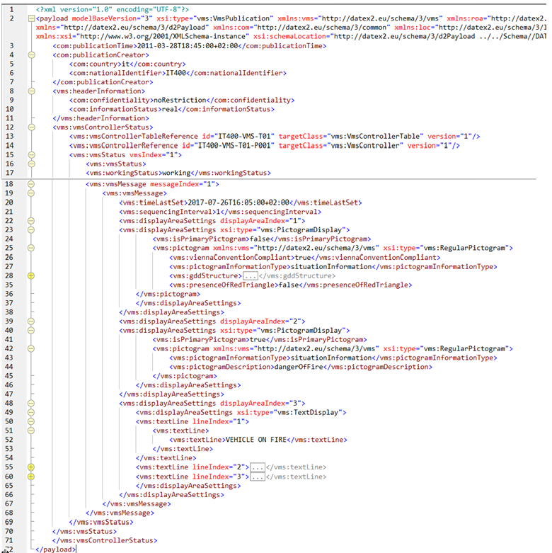
Figure: Double pictogram and textual area display information setting